[Top]
[Up]
[Prev]
[Next]
Semi-Rigid Main Rotors
A semi-rigid main rotor is always a 2 bladed rotor system. It gets its
name from the fact that it does not have a lead-lag hinge, the way a fully
articulated rotor system does. The rotor system can be said to be rigid
in-plane, because the blades are not free to lead and lag, but they are
not rigid in the flapping plane (through the use of a teeter hinge).
Therefore the rotor is not rigid, but not fully articulated either, so we
call it semi-rigid.
The rotor systems we will look at here are 2 bladed teetering systems. The
Robinson and the Bell teetering system differ because the Robinson includes
coning hinges in addition to the teeter hinge, while the Bell system simply
cones by bending the blades.
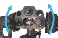
Basic R22 Head
Teeter Hinge
The dark blue arrow is pointing to the teeter hinge. This central hinge
allows the entire rotor head to tilt left and right in order to allow the
blades to flap. When one blade flaps up, the other flaps down. The entire
mechanical arrangement works like a child's see-saw (teeter-totter) toy.
Coning Hinge
The light blue arrows point to the two coning hinges. These hinges allow
each blade to move up and down independently of the other blade. This would
normally happen during coning, when each blade moves up until centrifugal force
balances lift. During times of high lift, or low RPM, the blades will be
coned quite high, while during low lift or high RPM, the blades will tend to
be lower.
The holes in the rotor head above the coning hinges serve no purpose except
that they may be used to hoist the rotor system.
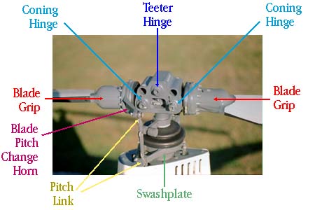
Blade Grips
The light red arrows point to the blade grip. The grip attaches the
rotor blade to the rotor head, and includes a pitch change mechanism used
to change angle of attack by feathering the blade (with the cyclic control).
In the case of the R22, the grip has multiple bearings, and is filled with
a fluid similar (identical?) to automatic transmission fluid.
Pitch Horn
The dark red arrow points to the left hand blade pitch horn. The pitch
horn on the right blade is behind the head in this photograph can cannot be
seen, but does exist. The purpose of the pitch horn is to give the feathering
pitch change mechanism (cyclic/swashplate) a place to attach to the blade.
By sticking out from the blade, the pitch horn works as a lever, decreasing
the force it takes to change the angle of the blade. Note that it also has
the effect of changing the location on the swashplate where the pitch
mechanism attaches. Rather than attaching to the swashplate directly under
the blade, it attaches to the swashplate almost 90 degrees earlier in rotation.
This is how the control system corrects for the almost-90 degree lag in rotor
response due to Gyroscopic Precession.
Pitch Link
The yellow arrow points to the pitch link, which connects the pitch horn
to the swashplate. These length of these pitch links can be adjusted to set
the angle of incidence of the blade during track and balance of the rotor
system.
Rotating Star (Swashplate)
The green arrow points to the rotating portion of the swashplate, which
attaches to the pitch links. Below that is the non-rotating part, which
connects to the pitch control rods coming up from the cyclic/collective
mixer.
Basic JetRanger (Bell 206) Head
The design of the Bell 206 rotor head is not that different from that of
the Robinson. Note that in this picture, there are no light blue arrows,
because the 206 head does not include coning hinges. Instead, the rotor
head is designed with a pre-cone angle to the blade retention system, and
other coning forces are simply dealt with by bending of the blades (which
must be built stronger to deal with the extra stress).
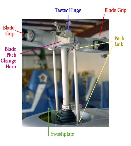
Blade Grips
The light red arrows point to the blade grips. The design is slightly
different than the Robinson. The inside of the grips is filled with a light
grease, rather than a fluid. Also, note on the right hand blade that there
is a vertical bolt attaching the blade to the grip. The blade can be set
with some fixed lead or lag as part of the rotor system rigging, compared
to the Robinson where the lead/lag position of the blade is fixed by the
design of the rotor head, and can not be adjusted, even at the factory.
What is Teetering (Flapping) versus Feathering?
On any rotor system, flapping occurs when the blade moves up and down. On
a rigid rotor system, this occurs when the blade bends. On an articulated
system, the blade flaps up and down around a flapping hinge. On a
2 bladed, semi-rigid teetering system, the blades flap in unison around
the flapping hinge such as in these pictures of a Robinson R22:
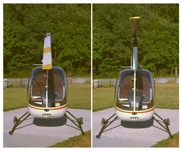
Notice that the angle the airfoil makes with the horizon here does not change.
Flapping changes the angle of attack not by pitching the airfoil up or down,
but by changing the direction of the wind relative to the blade. For a more
in-depth discussion see Relative Wind,
Flapping and
Angle of Attack.
Compare this to the following picture which shows the blade being feathered
by the pilot's controls via the swashplate:
In this picture, you can clearly see that the angle of the blade with respect
to the horizon has changed, from a nose up angle on the left side, to a nose
down angle on the right side. In this case, the swashplate has moved in
response to either the cyclic, collective, or both, and has moved the pitch
links up or down. Since the pitch links are connected to the blade via the
pitch horn, the blade is forced to rotate around the blade grip bearing
into a different angle
of incidence.
How does the Rotor System Teeter?
The rotor system teeters around the central hinge. The position of the
blades is due to the balance between centrifugal force which is trying
to hold the blades "straight out", versus lift which is trying to make
them fold straight up. The balance of the forces will cause the blades
to fly at some angle. If one blade starts to develop more lift, while
the other blade starts to develop less lift, one blade will want to climb
while the other will want to descend. The result will be that the rotor
head will teeter, allowing one blade to go up while the other goes down.
It is important to understand that teetering happens "automatically", as
a result of aerodynamic and centrifugal forces. The pilot does not command
flapping with the control system.
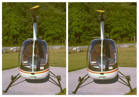
How does (the R22) Control System Transmit Pitch to the Blades?
There are many different mechanisms for transmitting cyclic and collective inputs
to the main rotor system. The Robinson R22 and R44 mount the swashplate on a
monoball. This allows the entire swashplate to slide up and down on the
rotor mast (for collective inputs) and tilt (for cyclic inputs).
These two pictures show how the swashplate slides up and down to transmit
a collective pitch change:
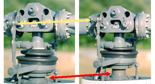
You can see that the red arrow is pointing to the bottom of the swashplate
in the left hand picture, but that in the right hand picture the entire
swashplate has moved up the mast. Notice the effect that has on the pitch
links: the yellow arrows show that in the right hand picture, the pitch
link has moved up along with the swashplate (compare the top of the pitch
link and the left hand coning hinge bolt in the two pictures). Since the entire
swashplate has moved up without changing its tilt, the pitch links have all
moved up a set amount, but will continue to move up and down during rotation
in response to the tilt of the swashplate.
In comparison, look at the following picture to see how cyclic input is
transmitted to the blades:

Notice that the swashplate in the left hand photograph is basically level,
while in the right hand photograph it has been tilted. The tilt will cause
the pitch link to have to move up as it travels to the right hand side of the
picture, and move back down as it travels to the left hand side of the picture.
As it moves up and down the blade pitch will increase and decrease.
Paul Cantrell
paul at copters.com
(replace " at " with "@" to email me - this avoids SPAMMERS I hope)
[Top]
[Up]
[Prev]
[Next]