There are still several production helicopters which use multiple counterrotating rotors as a way to cancel out torque. Examples are the Boeing-Vertol tandem rotor helicopters which evolved from Frank Piaseki's designs, Charles Kaman's intermeshing rotor system, and the Russian co-axial helicopter (Hocum or Havoc I think it is, I'll have to look up the correct name I'm afraid). The V22 tilt-rotor uses counter-rotating proprotors in order to cancel out torque. It is similar to a tandem rotor system when in helicopter mode.
Igor Sikorsky seems to be the first to settle on using a single rotor mounted at the rear of the helicopter as a way to counter the torque. This is the most popular arrangement today. Sikorsky actually experimented with many different arragements before selecting a single tail mounted rotor.
It seems strange that the majority of helicopters produced use this method of countering torque, given that there are several major problems with this method which are not encountered with counter-rotating rotor systems.
One major problem with tail rotors is that they rob an enormous amount of power. As a rule of thumb, tail rotors consume up to 30% of the engine power.
Another probem is that due to size and weight constraints, tail rotors are fairly delicate compared to main rotors. This means that they cannot survive an encounter with very large obstacles. Because they are mounted at the rear of the helicopter, out of the pilot's sight, a fairly common cause of helicopter accidents is hitting an obstacle with the tail rotor, losing all anti-torque capability, and crashing due to the rotation of the entire helicopter.
Still another problem with tail rotors is that they are fairly difficult to
control accurately. Turbulence and crosswinds make it extremly difficult to
hold a constant heading in a tail rotor equipped helicopter. The workload
is very high, and good results are difficult to achieve. Many larger
helicopters end up being designed with a yaw stabalization system, which
is essentially an autopilot for the tail rotor.
Tail rotors experience
dissymetry of lift
just as a main rotor system does. (tail rotor dissymetry of lift is
discussed
specifically
in in the dissymetry of lift aerodynamics section). This lift dissymetry
would cause a torque around the tail boom which would tend to roll the
fuselage in the same direction as main rotor lift dissymetry. While cyclic
pitch could be used to counter the rolling tendancy, the tail rotor blades
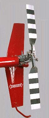
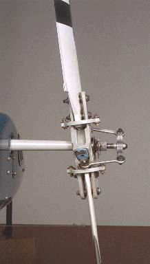
are typically allowed to flap, eliminating the lift dissymetry. Here is a
picture of a Bell 206 JetRanger tail rotor flapped to right and left
extremes:
There is no aerodynamic solution to this problem, and this is just one of the items which makes a tail rotor helicopter more difficult to fly. One solution which is sometimes used is a yaw-damper, essentially an auto-pilot which uses a gyroscope to detect uncommanded yaw, and which changes tail rotor pitch in order to prevent uncommanded yaw.
The solution to this problem is similar to that for the main rotor: try to prevent it from happening, but if it does either move the tail rotor into clean air (by moving the helicopter), autorotate (to eliminate the torque) or try to get out of the ring vortex state by a very rapid and large increase in thrust (but if the pedal is already at the stop, this probably isn't possible). A hover auto is probably the safest, most reliable way to get out of this situation.
The angle of attack of the tail rotor is controlled by the pilot's anti-torque pedals (they're not "rudder pedals" in a helicopter). The pedals are typically connected to the pitch change mechanism by either push pull tubes, or by cables. From the standpoint of controlling pitch, a tail rotor requires collective pitch control, but not cyclic feathering. This makes the pitch control mechanism of most tail rotors much simpler than that of the main rotor system.
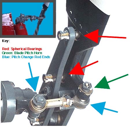
The tail rotor blades must be mounted, and there must be a mechanism to change the pitch of the blades. This picture is of a Robinson R22 tail rotor. You can clearly see how the blades are attached, and how the pitch change mechanism can pivot the blades.
The red arrows point at the attach points for the blade itself. These attach points are a bolt which goes from one side of the yoke, through the blade, and into the other side of the yoke. The spherical bearing itself allows the blade complete freedom to rotate around the ball, which the upper red arrow is pointing at. Because there are two of these spherical bearings (you can just see the second one that the lower red arrow is pointing at) the blade is constrained to only move around an axis which is aligned between the two bearings. This allows the blade's pitch (angle of attack) to be changed, but allows no other motion of the blade with respect to the yoke.
Notice that the bottom of the blade makes an "L" shape, with the green arrow pointing to the end of the "L" where a bolt goes through it. The "L" part of the blade, which I call a "Pitch horn", gives us some leverage to move the blade in pitch.
The bolt which goes through the "pitch horn" also goes through a pitch change rod end (right hand blue arrow) which has one of those spherical bearings in it. This allows the rod end to push and pull on the pitch horn, thereby changing the pitch of the blade.
The other end of the rod end (left side blue arrow) is attached to the pitch change yoke. This is examined in a later picture. Here is another picture of the same assembly, from a very slightly different angle. You can see the "L" shaped bottom of the blade better, and it's a little more obvious how it attaches to the pitch change rod.

Here is the same assembly, except that now we are standing behind the helicopter looking directly forward at the tail rotor assembly:

This picture shows how the pitch change mechanism works:
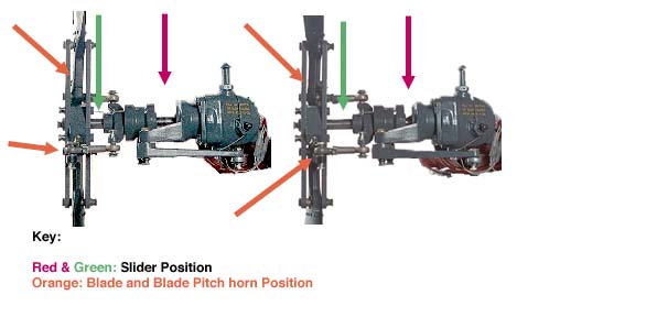
The red and green arrows show how the slider slides left and right on the shaft. The pitch change rods are connected to the slider, and so as the slider moves to the right, the pitch change rods move to the right, and take the blade pitch horn with them. If you look carefully at the bottom orange arrows, you can see that the pitch change rod and the blade pitch horn have been moved to the right. The upper orange arrow just points at the blade, which you can see is at a different pitch angle in the two pictures.
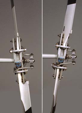
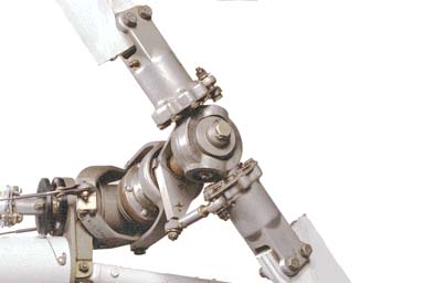
Here is the Bell 206 JetRanger tail rotor. Notice that the pitch change
mechanism is quite different than the R22. The pitch change rod is actually
a shaft which goes through the hollow shaft the tail rotor is mounted on:
Here is a closeup of the tail rotor hub at two extreme pitch settings. In the left hand picture, the red arrow shows that the inner shaft has been extended all the way to the right. The right hand picture shows the same shaft has been retracted:
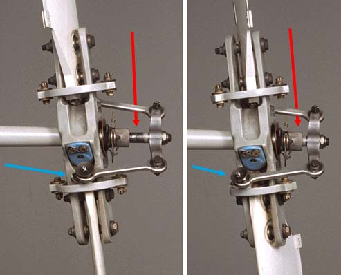
As the inner shaft slides left and right, the pitch change rods are dragged along, and pulls the blade pitch change horn along with it. The blue arrow points out how far the rod end has moved, taking the blade's leading edge with it. Like the Robinson, the blade is mounted on two spherical bearings, which cause it to rotate only in the pitch axis.
This is the Enstrom F28A tail rotor assembly. In the lower left corner of the picture, you can see the cable attaching to the pitch change mechanism. The Enstrom blades don't attach with spherical bearings the way the Robinson and Bell do, they utilize a bearing pack to allow the blade to feather.